Article Text

Abstract
Ensuring proper placement of epidural catheters is critical to improving their reliability for pain control and maintaining confidence in their continued use. This article will seek to address the role of objective confirmation of successful epidural placement via either single view or continuous epidural contrast studies, each creating an ‘epidurogram.’ Furthermore, the pertinent anatomical corollaries of continuous fluoroscopy used frequently in chronic pain medicine, from which these techniques emerged, will be addressed. Technical radiographic information needed to better understand and troubleshoot these studies is also included. Image examples which highlight the patterns key for successful interpretation of epidurograms will be provided. The aim of this paper was to provide an anesthesiologist unfamiliar with fluoroscopic evaluation of epidural catheters with the tools necessary to successfully conduct and interpret such an examination.
- Pain, Postoperative
- Pain Management
- Diagnostic Techniques and Procedures
- Acute Pain
- REGIONAL ANESTHESIA
Data availability statement
Data sharing not applicable as no datasets were generated and/or analyzed for this study. This article serves as an educational article and does not include the implementation or analysis of novel datasets. As such, no datasets were generated or analyzed for this publication.
Statistics from Altmetric.com
Introduction
Epidural analgesia has for decades been considered the ‘gold standard’ for postoperative pain control in major abdominal and thoracic surgery.1 Unfortunately, a lack of widely accessible methods for confirming objective success has likely contributed to the high failure rate,2 thereby limiting its clinical efficacy. Epidurograms, which are fluoroscopic contrast evaluations of the epidural space, can identify both correctly placed and misplaced epidural catheters, potentially improving perioperative analgesia.3 4 This article will provide an overview of epidurogram acquisition, interpretation and troubleshooting. The authors hope this educational resource will improve familiarity with these exams so that this technique may gain more widespread adoption.
Technical steps of a fluoroscopically placed epidural
Fluoroscopy is considered to be the gold standard for objective verification of successful neuraxial procedures and has demonstrated its ability to confirm epidural catheter placement.4 The findings obtained by continuous fluoroscopy and single-view contrast injections into the epidural space (epidurograms) can definitively identify both correct and incorrect epidural catheter location. In a continuous fluoroscopically guided epidural procedure, a posterior–anterior (PA) image is frequently first obtained to locate midline and to identify vertebral levels. With the spinous processes aligned along their associated vertebral bodies, a needle entry point and trajectory to serve as a conduit for epidural catheter insertion are selected. The needle is advanced within the selected approach under intermittent fluoroscopic guidance until the proceduralist notes a tactile change in tissue density at the needle, which often corresponds with engagement of the needle in the dense ligamentum flavum. Often, the angle of fluoroscopy is then directed lateral or in a contralateral oblique view at 45°–55° by rotating the X-ray head to demonstrate true needle position in the ligamentum flavum just at or beyond the ventral laminar line. This additional view provides another perspective (depth), helping to confirm proper needle alignment for entry into the epidural space. Entry into the epidural space is then supported by the standard loss of resistance technique via a saline-filled or air-filled syringe. Once loss of resistance is obtained, an epidural catheter is advanced under continuous fluoroscopy to the target destination based on the specific surgical procedure. At this point, an iodinated contrast injection through the inserted catheter can be performed. Imaging of contrast can be performed with continuous fluoroscopy (ie, watching the dye kinetically move during injection), or by taking a single-view post-injection.
Epidural contrast injection interpretation
Once images are obtained, understanding common patterns of contrast spread can facilitate evaluation of epidural catheter placement. On PA imaging via single view or continuous imaging, contrast spread patterns can be characterized in one of several categories that help to confirm or disprove epidural tip location within the epidural space. If the catheter is in the epidural space, the dye will typically appear diffusely dispersed with opacification appearing to spread circumferentially around the epidural space and extending along the proximal nerve sheaths (figure 1). This is often referred to as a ‘wraparound’ spread pattern and is reassuring of epidural catheter tip location, and can be further supported by a lateral spine image. The injected iodinated contrast agent may also form a ‘honeycomb’ pattern of partial dispersion throughout the interstices of epidural fat, which is also supportive of epidural spread of contrast (figure 1). Finally, contrast injected epidurally may be seen exiting the neuroforamen laterally on PA imaging (figure 1). A transforaminal approach may also depict the nerve sheath as being outlined by contrast, sometimes with proximal reflux.5 These patterns of ‘honeycombing’, ‘neuroforaminal exiting’ and contrast outlining the epidural space bounded by pedicles are each demonstrated in figure 1. In some cases, a lateral or contralateral oblique view can be used to assess an epidural catheter when an anteroposterior image is not definitive. When a lateral view is employed, contrast spreading in the epidural space will appear as tracking deep to the spinous processes yet superficial to the vertebral bodies (figure 2). We recommend identifying at least one of these radiographic signs to confirm that an epidural catheter is actually in the epidural space.

Posterior–anterior radiographs of the thoracic spine of two patients following iodinated contrast administration via epidural catheters. Partial diffusion of contrast throughout the fatty lobules of the epidural space creates a ‘honeycomb’ pattern of opacification (white arrows) with lateral segmental extensions along the expected locations of the exiting nerve roots (black arrows). A ‘wraparound’ spread of contrast throughout the epidural space at both high thoracic (A, T-4 tip location) and lower thoracic (B, T-10 tip location) appears and could be further clarified with lateral imaging.

Lateral radiograph of the thoracic spine following iodinated contrast administration via epidural catheter (yellow arrows). Catheter and dye can be seen deep to the spinous processes and superficial to the vertebral bodies. Correct epidural catheter location may be in either the posterior epidural space (A) or the anterior epidural space (B). Contrast dye spreads several levels in each direction from the catheter tip (white arrows).
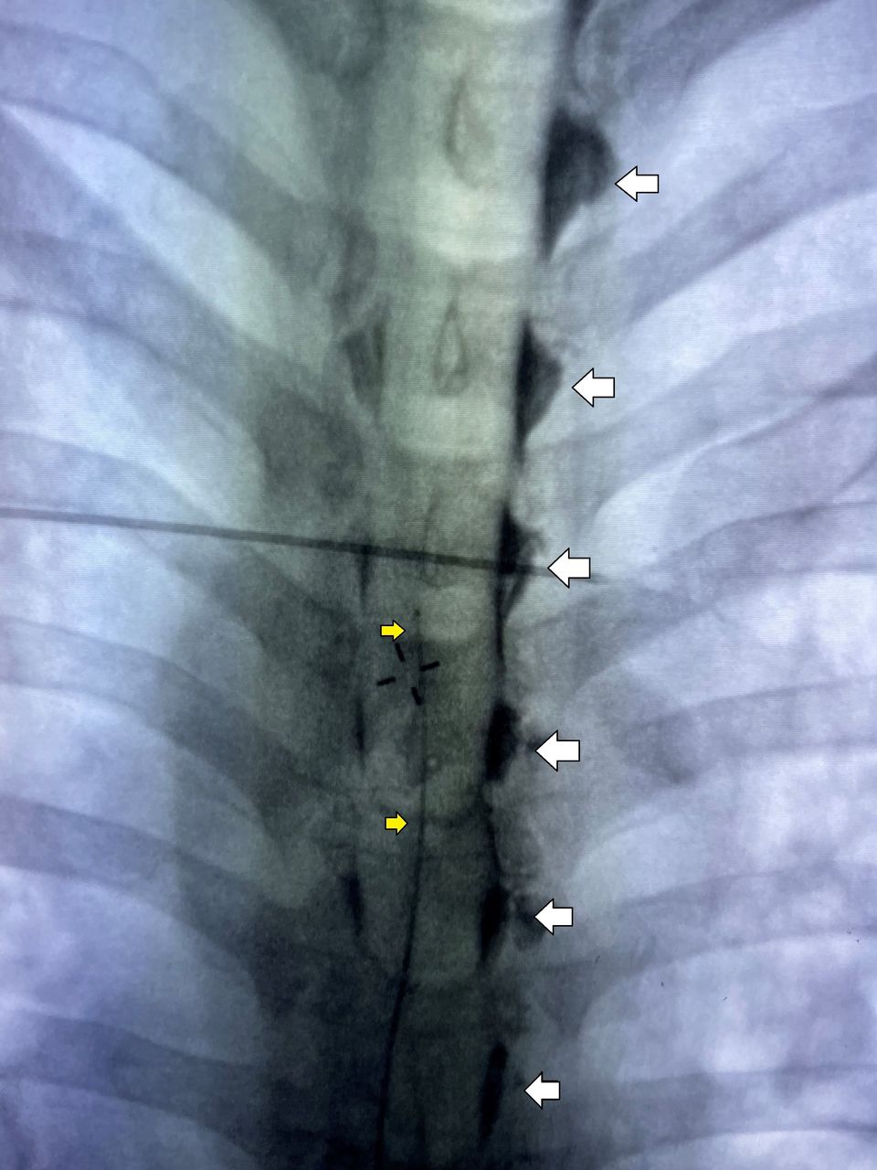
Malpositioned or misplaced epidural catheters within the subdural and/or subarachnoid spaces demonstrate unique iodinated contrast agent opacification patterns that differ from the wraparound and honeycomb epidural pattern. Subarachnoid injections opacify the intrathecal space (figure 3), while the less common subdural injection will only opacify dural margins (figure 4). The dye spread in the intrathecal space is often extensive, throughout the spine, as it is uninhibited by epidural fat globules and freely moves in the cerebrospinal fluid. Such images do not have the same wraparound appearance but instead fill the image within the spine in a solid dorsal to ventral band of contrast without honeycombed interruptions (figure 3). The resultant ‘glasslike’ patterns of undulating opacity depict the lateral-most margins of these spaces, where ventral and dorsal nerve roots penetrate the dura at the ‘subarachnoid angles’.6 7 Given that intrathecal contrast will often rapidly dissipate, continuous fluoroscopic imaging will increase the ability to detect these changes prior to contrast dissipation. Subdural injections will not display the same midline dorsal to ventral banding. Subdural spread, by contrast, is often described as a ‘tram’ or ‘railroad track’ appearance as the contrast dye highlights linear ‘tracks’ that extend craniocaudally just medial to the pedicles (figure 4). Contrast in this space can be limited to one or both sides and is often demonstrated exiting from a nerve root, but does not typically occupy the midline (figure 4)

Posterior–anterior (A) and lateral (B) radiographs of an intrathecal catheter in the thoracic spine following administration of iodinated contrast. Dye rapidly diffuses from the catheter tip (white arrows) throughout the cerebrospinal fluid, collecting in the more dependent portion of the spine (black arrows). Fat globules and extension into exiting nerve roots are absent.

Posterior–anterior radiograph of the thoracic spine following injection of iodinated contrast through a catheter (yellow arrows) inadvertently placed into the subdural space. Contrast dye is seen only in the exiting nerve roots, predominantly on a single side (white arrows) with exaggerated cephalad and caudal extension over 8–10 levels. Absent are fat globules or the appearance of circumferential spread throughout the epidural space. A ‘tram track’ pattern is demonstrated extending cranial/caudal between each pedicle.
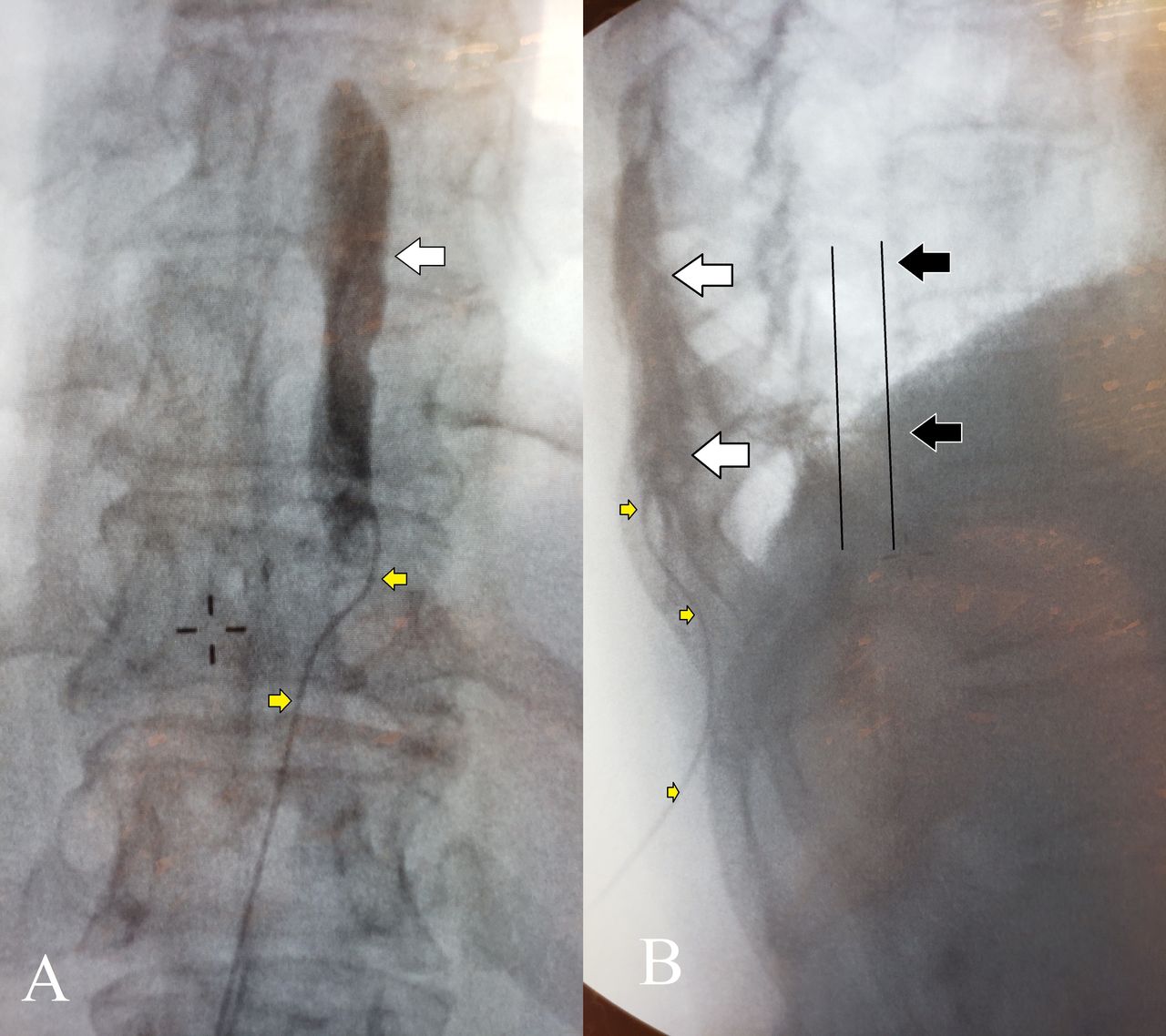
Injections which do not occur in either epidural, subdural or subarachnoid spaces may display quite unique contrast patterns. Malpositioned catheters may highlight adjacent contiguous spaces, such as the intercostal space or those inadvertently placed into muscular tissue outside the epidural space may actually show muscle striations within injected contrast (figure 5). What is important to remember is that these injections will not display characteristic epidural spread patterns. Anesthesiologists performing epidural procedures should confirm their findings by looking for contrast spread bound by vertebral pedicles, providing the wraparound filling of the epidural recess, and supported by negative contrast from epidural fat honeycombing, and possibly ‘tails’ of contrast exiting the neuroforamen.

AP (A) and lateral (B) radiographs of an improperly placed epidural catheter in the subcutaneous tissue of the thoracic spine following iodinated contrast administration via the epidural catheter (yellow arrows). In the AP image (A), there is an absence of fat globules or extension of dye (white arrows) into exiting nerve roots. The lateral image (B) shows the epidural catheter and dye superficial to all boney structures of the spine. The black arrows indicate the expected catheter and dye location of a properly positioned epidural catheter in a lateral image. AP, anterior–posterior.
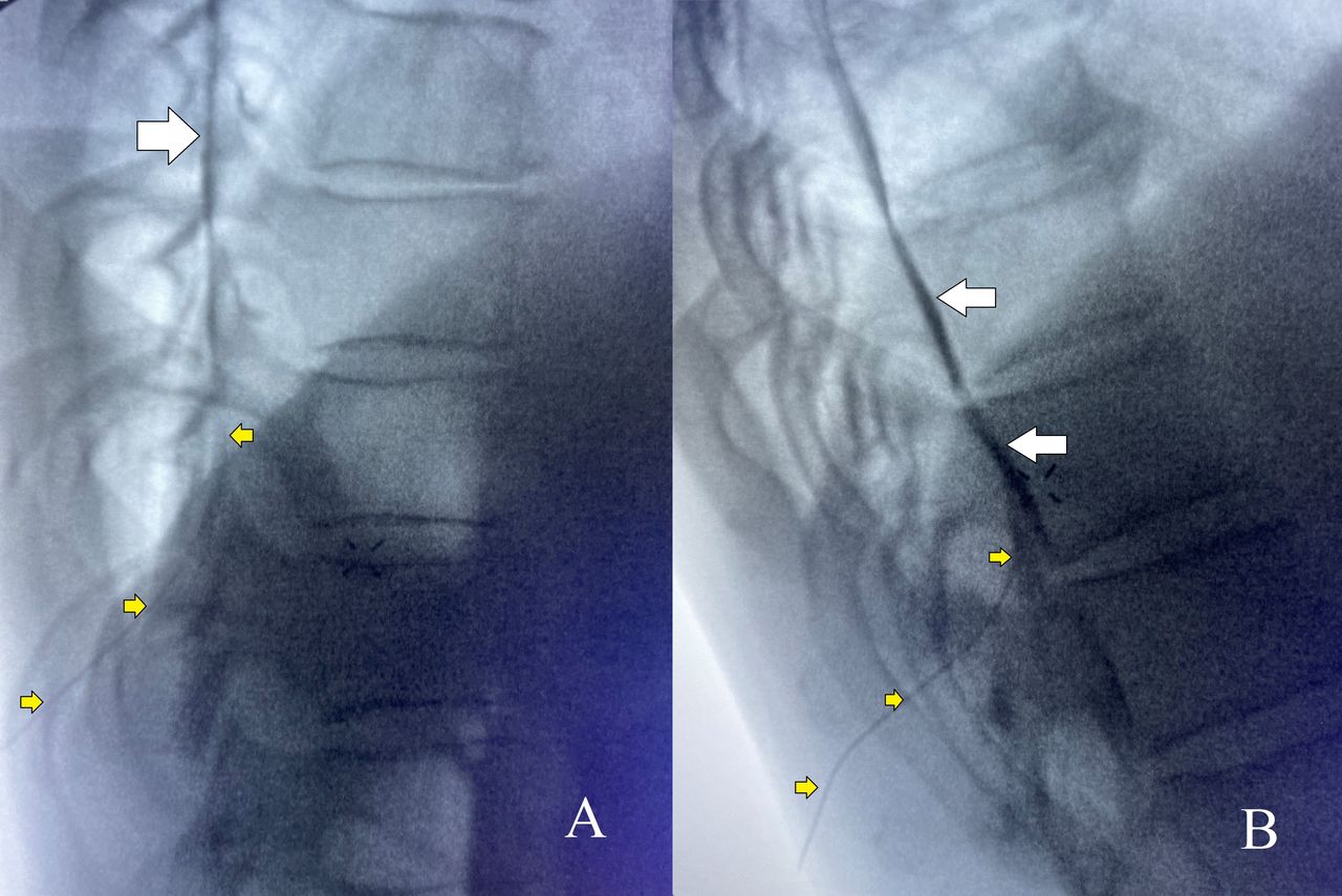
Intravascular placement of an epidural catheter is also possible and is of concern when performing neuraxial procedures. While epinephrine has traditionally been used in test dose medications to rule out this possibility, fluoroscopic findings can also aid in this diagnosis. Dye injected following intravascular injection is often ‘swept away’ into circulation and not evident on subsequent imaging taken immediately following contrast injection. On continuous fluoroscopy, contrast can sometimes be seen outlining the vasculature itself (figure 6). A lack of contrast visualization on fluoroscopy should raise the proceduralist’s suspicion for this kind of catheter misplacement.

Posterior–anterior radiograph of the thoracic spine following injection of iodinated contrast (A) and during continuous imaging injection of iodinated contrast (B) through the intravascular epidural catheter (yellow arrows). Dye is rapidly carried away via the blood vessel, and an image taken seconds after injection (A) exhibits a complete absence of contrast. Injection under continuous imaging fluoroscopy (B) reveals the vascular dye uptake (white arrows).
Clinical considerations for use of epidurography
Epidural catheters are often employed in the field of acute pain medicine to administer local anesthetic or opioids. Fluoroscopic evaluation of the epidural catheter can provide definitive, visible confirmation of the epidural catheter’s course into the epidural space. Additionally, catheter tip location can be assessed under fluoroscopy, allowing for proper placement at the dermatomal site of the operator’s choice. The success of thoracic epidural analgesia is dependent on the catheter’s position within the epidural space. Of equal importance, however, is catheter tip placement in a region where infusate exiting the catheter can adequately diffuse to provide dermatomal coverage at the level of the surgical insult. Therefore, placement outside the epidural space, as well as placement at the wrong dermatomal location, can cause epidural catheter ‘failure’. As addressed previously, there is currently a high failure rate (approximately 25%)2 in the standard tactile, unconfirmed methods of epidural placement. Continuous fluoroscopy provides an associated significant improvement in the success rate of epidural placement that occurs with resulting decreases in post anesthesia care unit (PACU) time and hospital length of stay.4 Epidurography using continuous fluoroscopy offers the benefit of real time needle guidance and the ability to detect subtle dye pattern changes that may assist in identifying inadvertent intrathecal catheter placement or indicate intravascular uptake of injectate in real time. If the resources for continuous fluoroscopy are not available, epidurography may also be conducted using a single-view technique postprocedurally. Such a study does not offer real-time needle guidance; however, it may be advantageous in locations where a coaxial fluoroscopy unit is not available, can be conducted in most locations with a simple portable X-ray unit and exposes the patient to less ionizing radiation.3
Regardless of the technique used, an understanding of radiation dosing is essential to ensure safety of patients and staff. In an adult, the effective patient dose for a thoracic spine radiograph is approximately 1 mSv. A 25-year-old patient receiving a 1 mSv effective dose of energy will see a lifetime risk of developing any form of cancer potentially increase from 40.0% to 40.01%.8 This dose of ionizing radiation imparted from a single view radiograph is roughly equivalent to 10 days of normal environmental background exposure. In pediatric patients, due to the theoretical risks posed to young, developing organs, exceptional care must always be taken to further limit ionizing radiation exposure. Acquiring multiple views of a pediatric patient should not be routinely performed if a single view is deemed sufficient.9 Given the physics of exponential radioactive decay, the risks to bystanders who are a mere feet from the imaged patient are minuscule for a single-view, postprocedural epidurography study. If continuous fluoroscopy is employed, the duration of active imaging should be monitored and the total dose of radiation should be minimized. Appropriate shielding should also be considered.
Radiographic considerations
Key to the successful employment of epidurography is understanding the nuances of radiography. Clinicians performing these exams must have an understanding of how images using iodinated contrast agents are optimized in order to improve image quality and interpretation. The injectate used in epidurography typically consists of 3–5 mL of iodinated contrast agent at 240 mg/mL concentration to confirm successful epidural positioning. By comparison, contrast-enhanced CT scans routinely employ an intravenous injection of 60–100 mL iodinated contrast agent at 300–350 mg/mL. Due to small-volume dosing, adverse events from the use of iodinated contrast agent for epidurography are rare and effectively limited to allergic reactions. Estimated rates of allergic reaction to iodinated contrast agent use for CT imaging are approximately 0.6% (0.04% severe).10 Most reactions are mild and are prevented or mitigated with steroid and antihistamine pretreatment protocols. Given the small volume of contrast injected, it is unlikely symptoms of those with diabetes or renal insufficiency would be exacerbated; however, patient data are lacking. While intravenous injection of contrast can occur, a preservative-free contrast agent injected intravascularly in the volumes discussed is typically well tolerated. An intravascular injection would be demonstrated as a tortuous contrast pattern highlighting the vessel in which it is injected and then subsequently dispersed into circulation. In patients considered too high risk for severe iodinated contrast agent reactions, pretreatment against contrast allergy could be considered, but the data for such an intervention is admittedly lacking.
Most fluoroscopic C-arms and radiology procedural suites are calibrated to optimize visualization of iodinated contrast agents during procedures. However, mobile X-ray units used for portable epidurography may not sufficiently depict the injected iodinated contrast agent (ICA), depending on the X-ray tube settings. The K-edge of iodine is approximately 33.2 keV, which means X-ray beam attenuation occurs best at X-ray energy levels of 33–40 keV. Due to the polychromatic nature of X-ray tubes, a kvP setting of 60–80 will typically achieve this desired range. Image inversion (black–white reversal) if available, may also increase iodinated contrast agent conspicuity.
Conclusions
An epidurogram is a radiographic contrast study that provides an immediate confirmation of epidural catheter location. Such information should eliminate malpositioned catheters that are in either ineffective or dangerous locations.
Data availability statement
Data sharing not applicable as no datasets were generated and/or analyzed for this study. This article serves as an educational article and does not include the implementation or analysis of novel datasets. As such, no datasets were generated or analyzed for this publication.
Ethics statements
Patient consent for publication
Footnotes
Contributors All authors assisted in the design and contributed to the final manuscript.
Funding The authors have not declared a specific grant for this research from any funding agency in the public, commercial or not-for-profit sectors.
Competing interests None declared.
Provenance and peer review Not commissioned; externally peer reviewed.